I want to use an Raspberry Pi 400 (the keyboard thing) as the
dev/debug system for an RP2040 based product.
https://www.amazon.com/Raspberry-Computer-Keyboard-Layout-Kabel/dp/B08QCQVWH2
It has a 40-pin connector on the back. Various sources say that pins 1
3 and 5 are either GPIO ports 8 9 and 7 or maybe 2 3 and 4.
Sometimes the pins are labeled WPI and BCM. Wot's that?
https://www.amazon.com/Coolwell-Waveshare-Raspberry-Adapter-Expansion/dp/B08RZCR7S8
I can fix most mistakes there in software, just by reassigning port
names. But two pins are critical, the SWDIO and SWCLK debug lines out
to a Pi Pico or to the 2040 chip.
I suspect that on the Pi 400 pin 18 is GPIO5 = SWDIO and pin 22 is
GPIO6 = SWCLK.
Is that right? Does that actually work?
I also note that some people also connect the UART tx/rx between the
Pi400 and a Pico for debugging. Should I do that too? Does it help
software development?
Thanks!
"John Larkin" <jjlarkin@highlandtechnology.com> wrote in message news:d21ibjdvt6odqium3ado62ob1e7sa6n9hc@4ax.com...
I want to use an Raspberry Pi 400 (the keyboard thing) as the
dev/debug system for an RP2040 based product.
https://www.amazon.com/Raspberry-Computer-Keyboard-Layout-Kabel/dp/B08QCQVWH2
It has a 40-pin connector on the back. Various sources say that pins 1
This connector?
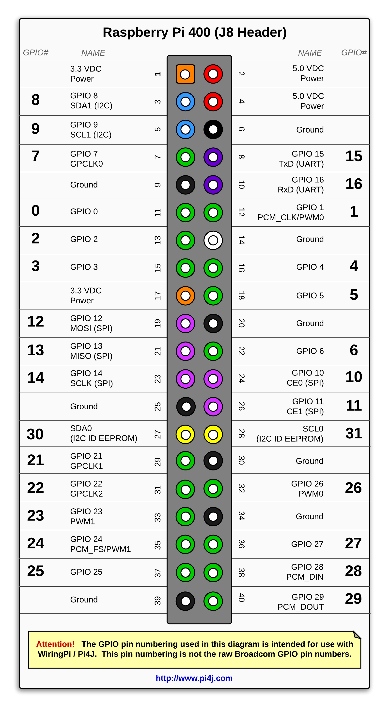
https://www.pi4j.com/1.3/images/pi4j-rpi-400-pinout.png
3 and 5 are either GPIO ports 8 9 and 7 or maybe 2 3 and 4.
Sometimes the pins are labeled WPI and BCM. Wot's that?
https://www.amazon.com/Coolwell-Waveshare-Raspberry-Adapter-Expansion/dp/B08RZCR7S8
If that's just a connector then continuity check it to the above drawing of the connector on the Pi.
I want to use an Raspberry Pi 400 (the keyboard thing) as the
dev/debug system for an RP2040 based product.
https://www.amazon.com/Raspberry-Computer-Keyboard-Layout-Kabel/dp/B08QCQVWH2
It has a 40-pin connector on the back. Various sources say that pins 1
3 and 5 are either GPIO ports 8 9 and 7 or maybe 2 3 and 4.
Sometimes the pins are labeled WPI and BCM. Wot's that?
https://www.amazon.com/Coolwell-Waveshare-Raspberry-Adapter-Expansion/dp/B08RZCR7S8
I can fix most mistakes there in software, just by reassigning port
names. But two pins are critical, the SWDIO and SWCLK debug lines out
to a Pi Pico or to the 2040 chip.
I suspect that on the Pi 400 pin 18 is GPIO5 = SWDIO and pin 22 is
GPIO6 = SWCLK.
Is that right? Does that actually work?
I also note that some people also connect the UART tx/rx between the
Pi400 and a Pico for debugging. Should I do that too? Does it help
software development?
On Sun, 11 Aug 2024 16:22:04 -0400, "Edward Rawde"
<invalid@invalid.invalid> wrote:
"John Larkin" <jjlarkin@highlandtechnology.com> wrote in message news:d21ibjdvt6odqium3ado62ob1e7sa6n9hc@4ax.com...
I want to use an Raspberry Pi 400 (the keyboard thing) as the
dev/debug system for an RP2040 based product.
https://www.amazon.com/Raspberry-Computer-Keyboard-Layout-Kabel/dp/B08QCQVWH2
It has a 40-pin connector on the back. Various sources say that pins 1
This connector?
https://www.pi4j.com/1.3/images/pi4j-rpi-400-pinout.png
Yes.
3 and 5 are either GPIO ports 8 9 and 7 or maybe 2 3 and 4.
Sometimes the pins are labeled WPI and BCM. Wot's that?
https://www.amazon.com/Coolwell-Waveshare-Raspberry-Adapter-Expansion/dp/B08RZCR7S8
If that's just a connector then continuity check it to the above drawing of the connector on the Pi.
The real question is whether pin 3 is GPIO8 or GPIO2, and which two
pins are the SW debug.
On the Pi4, pin 3 is GPIO2.
It seems like the pins are renamed on the
Pi 400, where pin 3 is GPIO8. Why would they do that?
On Sun, 11 Aug 2024 16:22:04 -0400, "Edward Rawde"
<invalid@invalid.invalid> wrote:
"John Larkin" <jjlarkin@highlandtechnology.com> wrote in message news:d21ibjdvt6odqium3ado62ob1e7sa6n9hc@4ax.com...
I want to use an Raspberry Pi 400 (the keyboard thing) as the
dev/debug system for an RP2040 based product.
https://www.amazon.com/Raspberry-Computer-Keyboard-Layout-Kabel/dp/B08QCQVWH2
It has a 40-pin connector on the back. Various sources say that pins 1
This connector?
https://www.pi4j.com/1.3/images/pi4j-rpi-400-pinout.png
Yes.
3 and 5 are either GPIO ports 8 9 and 7 or maybe 2 3 and 4.
Sometimes the pins are labeled WPI and BCM. Wot's that?
https://www.amazon.com/Coolwell-Waveshare-Raspberry-Adapter-Expansion/dp/B08RZCR7S8
If that's just a connector then continuity check it to the above drawing of the connector on the Pi.
The real question is whether pin 3 is GPIO8 or GPIO2, and which two
pins are the SW debug.
On the Pi4, pin 3 is GPIO2. It seems like the pins are renamed on the
Pi 400, where pin 3 is GPIO8. Why would they do that?
I want to use an Raspberry Pi 400 (the keyboard thing) as the
dev/debug system for an RP2040 based product.
https://www.amazon.com/Raspberry-Computer-Keyboard-Layout-Kabel/dp/B08QCQVWH2
It has a 40-pin connector on the back. Various sources say that pins 1
3 and 5 are either GPIO ports 8 9 and 7 or maybe 2 3 and 4.
Sometimes the pins are labeled WPI and BCM. Wot's that?
https://www.amazon.com/Coolwell-Waveshare-Raspberry-Adapter-Expansion/dp/B08RZCR7S8
I can fix most mistakes there in software, just by reassigning port
names. But two pins are critical, the SWDIO and SWCLK debug lines out
to a Pi Pico or to the 2040 chip.
I suspect that on the Pi 400 pin 18 is GPIO5 = SWDIO and pin 22 is
GPIO6 = SWCLK.
Is that right? Does that actually work?
I also note that some people also connect the UART tx/rx between the
Pi400 and a Pico for debugging. Should I do that too? Does it help
software development?
Thanks!--
In article <d21ibjdvt6odqium3ado62ob1e7sa6n9hc@4ax.com>,
John Larkin <jjlarkin@highlandtechnology.com> wrote:
I want to use an Raspberry Pi 400 (the keyboard thing) as the
dev/debug system for an RP2040 based product.
It has a 40-pin connector on the back. Various sources say that pins 1https://www.amazon.com/Raspberry-Computer-Keyboard-Layout-Kabel/dp/B08QCQVWH2 >>
3 and 5 are either GPIO ports 8 9 and 7 or maybe 2 3 and 4.
Sometimes the pins are labeled WPI and BCM. Wot's that?
https://www.amazon.com/Coolwell-Waveshare-Raspberry-Adapter-Expansion/dp/B08RZCR7S8
I can fix most mistakes there in software, just by reassigning port
names. But two pins are critical, the SWDIO and SWCLK debug lines out
to a Pi Pico or to the 2040 chip.
I suspect that on the Pi 400 pin 18 is GPIO5 = SWDIO and pin 22 is
GPIO6 = SWCLK.
Is that right? Does that actually work?
I also note that some people also connect the UART tx/rx between the
Pi400 and a Pico for debugging. Should I do that too? Does it help
software development?
Is the schematics from the R Pi 400 not available?
I have the orangepi 800. The schematics are such that I can trace the >connector pins to the soc pins. The RK3399 is fully documented.--- Synchronet 3.19b-Win32 NewsLink 1.113
Mapping the io I can do "das blinken light" on the 26 pin (rp1
compatible) connector, using ciforth (a Forth developed by me).
Or light the upper case or numlock leds.
Thanks!
Yes, but the port pin nunbering is different from the Pi 4 and 5, so I
was concerned about which pins to connect to a Pico (or a 2040 chip)
for program loading and debugging.
This apparently works
https://www.dropbox.com/scl/fi/sd8mkqz3rw55fcevjouvi/OKdo_Pi400_debug_Pico.jpg?rlkey=kb5xjo75n5e5k3ncy4qs2caur&raw=1
and one can actually count the pins on the connectors.
One of my guys is hacking some connections and verifying. We're laying
out some PCBs for debugging and production test, and we need to get
the pins right.
| Sysop: | Steven Bennett |
|---|---|
| Location: | Phenix City, AL |
| Users: | 210 |
| Nodes: | 4 (0 / 4) |
| Uptime: | 139:29:17 |
| Calls: | 8,936 |
| Calls today: | 4 |
| Files: | 5,620 |
| Messages: | 46,122 |